


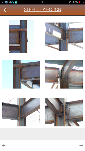
ဒီတစ္ခါ Structural Steel Connection ေတြထဲက Moment Connection အေၾကာင္း အင္ဂ်င္နီယာ ညီငယ္၊ ညီမငယ္ေတြ သတိထားမိေအာင္ နဲနဲ ေျပာျပမွာျဖစ္ပါတယ္။

Figure 1. Moment Connections Sample
Moment Connection ေတြအေၾကာင္းမေျပာခင္ Joint နဲ႔ Support ေတြအေၾကာင္း နဲနဲေျပာျပခ်င္ပါတယ္။
Joint ဆိုတာက member ႏွစ္ခု သို႔မဟုတ္ ႏွစ္ခုထက္ပိုၿပီး ဆက္ေနတယ့္ ေနရာပါ။ Joints ေတြထဲမွာ
1. Rigid Joint
2. Pinned Joint နဲ႔
3. Semi-Rigid Joint ဆိုျပီး ၃ မ်ဳိး ခြဲျခားႏိုင္ပါတယ္။
Rigid Joint
Rigid Joint ဆိုတာက Joint ကိုလာဆက္တဲ့ Member ေတြဟာ တစ္ခုနဲ႔တစ္ခု ခိုင္ျမဲစြာ (Rigidly) ဆက္စပ္ထားတဲ့ Joint တစ္ခု ျဖစ္ပါတယ္။ တနည္းအားျဖင့္ဆိုေသာ္ Connection ေတြမွာ Joint Deformation မျဖစ္ႏိုင္တဲ့ Joint မ်ိဳးျဖစ္ပါတယ္။ Joint Deformation ဆိုတာက Load သက္ေရာက္တဲ့အခါ Joint မွာ Yielding ျဖစ္ျပီး Member ႏွစ္ခုၾကားက အတြင္းေထာင့္တန္ဖိုး ေျပာင္းသြားျခင္း ျဖစ္ပါတယ္။ (ဥပမာ Beam Column Joint တစ္ခုမွာ Load သက္ေရာက္ျပီးေနာက္ Joint Member ႏွစ္ခုၾကားက အတြင္းေထာင့္ဟာ 90 Degree အျမဲရွိေနတဲ့ Joint မ်ဳိးျဖစ္ပါတယ္။) ဒါေပမယ့္ Load ေၾကာင့္ Joint တစ္ခုလံုးအေနနဲ႔ကေတာ့ as a whole အေနနဲ႕ rotation ျဖစ္ေပၚႏိုင္ပါတယ္။ Joint Rotation ျဖစ္ရျခင္းအေၾကာင္းက လာဆက္တဲ့ Member ေတြရဲ႕ Relative Stiffness ကို မူတည္ျပီး ျဖစ္ေပၚတာ ျဖစ္ပါတယ္။ ေအာက္ကပံုက Rigid Joint တစ္ခုရဲ႕ပံုျဖစ္ပါတယ္။

Figure 2. Rigid Joint
Pinned Joint
Pin Joint ဆိုတာကေတာ့ Member Ends ေတြ Freely Rotation ျဖစ္ႏိုင္တဲ့ Joint မ်ဳိးျဖစ္ပါတယ္။ Joint ကို Pin နဲ႔လာဆက္တဲ့ Member ေတြ Freely rotate ျဖစ္ႏိုင္တဲ့ Joint မ်ဳိးပါ။ Member ေတြမွာ End Moment မရွိတဲ့ Joint မ်ဳိးျဖစ္ပါတယ္။
Semi Rigid Joint
Semi Rigid Joint ဆိုတာက Pin Joint နဲ႔ Rigid Joint အမ်ဳိးအစားႏွစ္ခုၾကားထဲက Joint ပံုစံမ်ဳိးျဖစ္ပါတယ္။ Joint တစ္ခုလံုးအေနနဲ႔ Rotation ျဖစ္ႏိုင္တဲ့အျပင္ Load ေၾကာင့္ ဆက္ေနတဲ့ member ႏွစ္ခုရဲ႕ၾကားက အတြင္းေထာင့္ ေျပာင္းသြားႏိုင္တဲ့ (Joint ရဲ႕ Rigidity ေၾကာင့္ Joint Deformation ျဖစ္သြားႏိုင္တဲ့) Joint မ်ိဳးျဖစ္ပါတယ္။ တနည္းအားျဖင့္ဆိုေသာ္ Joint ကိုလာဆက္ေနတဲ့ Member ေတြကို Connection ေတြက ၁၀၀% rotation restrain မလုပ္ေပးႏိုင္တဲ့ Joint အမ်ဳိးအစားျဖစ္ပါတယ္။

Figure 3. Semi Rigid Joint
Supports
Support ဆိုတာက Member ေတြကို ေထာက္မထားတဲ့ ေနရာေတြကို ေခၚျခင္းျဖစ္ပါတယ္။ Support ေတြကို Theoretical အားျဖင့္ Roller, Pin နဲ႔ Fixed Supports ေတြရယ္လို႔ဆိုျပီး ခြဲျခားထားပါတယ္။
Pinned Support
Pin Support ဆိုတာက Member ရဲ႕ End Moment မရွိတဲ့ Support အမ်ဳိးအစားတစ္ခုျဖစ္ပါတယ္။ Member တစ္ခုဟာ Joint တစ္ခုကို Simple Connection နဲ႔ လာဆက္ရင္ အဲဒီ Member အတြက္ Pin Support အျဖစ္ယူဆႏုိင္ပါတယ္။ (Pin Supports ေတြအေၾကာင္းကို Simple Connection Notes မွာ ၾကည့္ႏိုင္ပါတယ္။)
Fixed Support
Fixed Support ကေတာ့ Member ေတြရဲ႕ End rotation ကို Fully restrained လုပ္ထားတဲ့ Support မ်ိဳးျဖစ္ပါတယ္။ ေအာက္ကပံုက Cantilever Beam တစ္ေခ်ာင္းအတြက္ End Rotation မရွိတဲ့ Fixed Support တစ္ခုရဲ႕ ပံုျဖစ္ပါတယ္။

Figure 4. Fixed Support
Actual Building Frame ေတြမွာေတာ့ Member ေတြရဲ႕ ဆက္ထားတဲ့ Joints ေတြဟာ rotation ျဖစ္ႏိုင္တာရယ္၊ Joint Deformation ျဖစ္ႏိုင္တာေတြရယ္ေၾကာင့္ Fixed Action ကို ရႏိုင္ဖို႔ ခဲယဥ္းပါတယ္။
ဥပမာအားျဖင့္ Column ေတြကို Effective Length ရွာတဲ့အခါ Column ေတြရဲ႕ Ends ေတြမွာ ဘယ္ေလာက္ Restraint ရွိလဲ (တနည္းအားျဖင့္ Fixity ဘယ္ေလာက္ရွိလဲ) ဆိုတာ ရွာဖို႔လိုအပ္ပါတယ္။ အဲဒီ Fixity ရမွသာ Column ရဲ႕ Effective Length ကို Code ေတြမွာ ေဖၚျပထားတဲ့ Graph ေတြကေန ျပန္ရွုာရမွာ ျဖစ္ပါတယ္။
Sample အေနနဲ႔ ေအာက္မွာ ေဖၚျပထားတဲ့ BS 5950 က Column Effective Length ရွာတဲ့ Graph ကို ေလ့လာႏိုင္ပါတယ္။ ဒီပံုကို ၾကည့္ျခင္းအားျဖင့္ Building Frame ရဲ႕ End Condition ေတြက အမ်ားအားျဖင့္ Pinned နဲ႔ Fixed အေျခအေန ၂ ခုၾကားမွာ ရွိတာကို ေတြ႕ရမွာပါ။ Pin နဲ႔ Fix က Boundary Condition အေျခအေန ႏွစ္ခု ပံုစံမ်ဳိး ျဖစ္ေနပါတယ္။ (ဒီ Graph ေတြအတြက္ Joint ေတြကို Rigid Joint အေနနဲ႕သာ စဥ္းစားတာ ျဖစ္ပါတယ္)။

Figure 5. Effective Length of Column as per BS 5950
ေအာက္က ပံုကေတာ့ AISC Code က Braced Frame အတြက္ Column Effective Length ရွာတဲ့ပံုပါ။

Figure 6. Effective Length of Column as per ANSI/AISC 360-10
Connection
Connection ဆိုတာက Member တစ္ခုကေန အျခားတစ္ခုကို ခံေဆာင္ရတဲ႔ အားေတြလႊဲေျပာင္းေပးရတဲ့ အဆက္ကို ေခၚျခင္းျဖစ္ပါတယ္။
(Connections are used to transfer the forces from one member to another)
Steel structure ေတြမွာ Connection Types ေတြအေနနဲ႔
1. Simple connection နဲ႔
2. Moment connection ဆိုၿပီး ႏွစ္မ်ိဳး႐ွိပါတယ္။
Simple connection က shear Force only ကို transfer လုပ္ၿပီး Moment Connection က Moment ေရာ shear Force ေရာ Bending Moment ပါ transfer လုပ္ေပးတဲ့ Connection မ်ဳိး ျဖစ္ပါတယ္။
အဲဒီ Moment connection ထဲမွာ transfer လုပ္ႏိုင္တဲ့ Moment ပမာဏကိုမူတည္ၿပီး rigid နဲ႔ semi-rigid ဆိုၿပီး ထပ္မံ ခြဲျခားႏိုင္ပါတယ္။
Actual Steel Frame Connections ေတြမွာ Simple, Rigid နဲ႔ Semi-Rigid Connections ေတြကို ေအာက္ပါအတိုင္း ေတြ႕ႏိုင္ပါတယ္။


Figure 7. Types of Connections
ဒီပံုကေတာ့ Structural Steel Moment Connection တစ္ခုမွာ End Moment ေၾကာင့္ Joint Deformation ျဖစ္ေပၚတဲ့ ပံုျဖစ္ပါတယ္။ ဒီလို Joint Deformation ျဖစ္ေပၚတဲ့အခါ Joint ဟာ Rigid မဟုတ္ေတာ့ဘဲ Semi-rigid ဘ၀ကို ေရာက္သြားပါတယ္။

Figure 8. Moment Connection: Joint Deformation
Rigid Connection တစ္ခုျဖစ္ေအာင္ Design ျပဳလုပ္ရာမွာ ထည့္သြင္း တြက္ခ်က္ရမယ့္ အခ်က္မ်ားစြာ ရွိပါတယ္။ ဒီ Post မွာေတာ့ Rigid Connection တစ္ခုကို ဘယ္လုိ Design လုပ္တယ္ဆိုတာထက္ Design/Detailing လုပ္ရာမွာ နဲ႔ Fabrication လုပ္သတိထားရမယ့္ အခ်က္ေလးေတြကို အထူးျပဳေရးသားသြားမွာ ျဖစ္ပါတယ္။
Structural Analysis လုပ္ရာမွာ Rigid လုိ႔ ယူဆျပီး လုပ္ထားတဲ့ Joints ေတြ Rigid အေျခအေနကေန ေလ်ာ့က်သြားတဲ့အခါ (Semi-Rigid အေျခအေန ေရာက္သြားတဲ့အခါ) Building Frame ရဲ႕ Behaviour ကလဲ Initial Assumed လုပ္ထားတဲ့ အေျခအေနနဲ႔ တူေတာ့မွာ မဟုတ္ပါဘူး။ အဲဒီလိုအေျခအေနမ်ဳိးဟာ Structure ရဲ႕ Stability ကုိေတာင္ Affect ျဖစ္ေစႏိုင္မွာ ျဖစ္ပါတယ္။ (ဥပမာအားျဖင့္ဆိုေသာ္ Portal Frame တစ္ခုမွာ Rigid Joint ေတြကို Pin အျဖစ္ေျပာင္းလိုက္ရင္ Stable မျဖစ္ေတာ့သလိုမ်ဳိးပါ။ ေအာက္က ပံုပါအတိုင္းျဖစ္ပါတယ္)။

Figure 9. Portal Frame Sample
ဒီေတာ့ Moment Connection တစ္ခု Design လုပ္ရာမွာ ထည့္သြင္းစဥ္းစားရမယ့္ အခ်က္ေလးေတြကို Extended End Plate Connection တစ္ခုကိုအေျခခံျပီး ေျပာျပသြားပါမယ္။
Extended End Plate Connection
ေအာက္ကပံုကေတာ့ Extended End Plate Moment Connection တစ္ခုမွာ ျဖစ္ေပၚတဲ့ Internal Stress ေတြကို သရုပ္ေဖၚရွင္းလင္းထားတဲ့ ပံုပဲ ျဖစ္ပါတယ္။ Stress Condition တစ္ခု Fail/Yielding ျဖစ္တာနဲ႔ Connection မွာ Deformation ေတြျဖစ္လာျပီးေတာ့ Rigid Connection အေျခအေနကေန ေလ်ာ့က် သြားႏုိင္ပါတယ္။

Figure 10. Extended End Plate Connection
ဒီ Connection မွာ
"a" က Bolt မွာျဖစ္လာတဲ့ Tension ပါ။ ဒီကေန No. of Bolt နဲ႔ Size of Bolt ကို Design လုပ္ရမွာျဖစ္ပါတယ္။
"b" ကေတာ့ End Plate ေပၚမွာျဖစ္လာတဲ့ Bending ကို ျပတာျဖစ္ပါတယ္။ End Plate ရဲ႕ Thickness ဘယ္ေလာက္လိုတယ္ဆိုတာကို ဒီကေန တြက္ယူရပါမယ္။ ဒါမွမဟုတ္ ေအာက္ကပံုအတိုင္း End Plate ကို Stiffener Plate ထည့္ေပးလို႔လဲ ရပါတယ္။

Figure 11 Extended End Plate Stiffener
"c" ကေတာ့ Tensile force ေၾကာင့္ Column ရဲ႕ Flange မွာ Bending ျဖစ္ေပၚတာျဖစ္ပါတယ္။ ဒီအတြက္ Tension Stiffener ကို ထည့္ေပးႏိုင္ပါတယ္။
"d" Tensile Force ေၾကာင့္ Beam ရဲ႕ Web မွာ ျဖစ္ေပၚတဲ့ Tension stress ျဖစ္ပါတယ္။
"e" က Column ရဲ႕ Web မွာျဖစ္ေပၚတဲ့ Tension Stress ျဖစ္ပါတယ္။ Column ရဲ႕ Web မွာ Tension Stiffener ထည့္ေပးႏိုင္ပါတယ္။ ေအာက္ကပံုက Tension Stiffener ထည့္ပံုျဖစ္ပါတယ္။

Figure 12 Tension Stiffeners
"f" ကေတာ့ Flange နဲ႔ End Plate ကို ဆက္ထားတဲ့ Weld ပါ။ Flange မွာ ျဖစ္ေပၚေနတဲ့ Tension Force ကို ခံႏိုင္ရည္ရွိေအာင္ Weld ကို Design လုပ္ရမွာ ျဖစ္ပါတယ္။
"g" ကေတာ့ Beam ရဲ႕ Web နဲ႔ End Plate နဲ႔ ဆက္ထားတဲ့ Weld ျဖစ္ပါတယ္။ Beam ရဲ႕ Shear Force ကို ထမ္းေဆာင္ႏိုင္ဖို႔ Design လုပ္ရမွာ ျဖစ္ပါတယ္။
"h" ကေတာ့ Connection က Moment (Tension at top flange and Compression at bottom flange) ေၾကာင့္ Column ရဲ႕ Web မွာ ခံေဆာင္ရတဲ့ Shear ျဖစ္ပါတယ္။
"j" ကေတာ့ Beam ရဲ႕ Flange က ခံေဆာင္ရတဲ့ Compression ပါ။
"k" က Beam ရဲ႕ Flange နဲ႔ End Plate ကို ဆက္ထားတဲ့ Weld ျဖစ္ပါတယ္။ ဒီ Connection မွာ Compression ထမ္းေဆာင္ရမွာ ျဖစ္ပါတယ္။
"l" က Column ရဲ႕ Web မွာ ခံေဆာင္ရတဲ့ Compressive Force ျဖစ္ပါတယ္။ Column ရဲ႕ Web က Beam ကေန သက္ေရာက္တဲ့ Compressive Force ကို မခံႏိုင္ဘူးဆိုရင္ Column ရဲ႕ Web မွာ Compression Stiffener ထည့္ေပးရမွာ ျဖစ္ပါတယ္။

Figure 13. Compression Stiffeners
"n" ကေတာ့ Bolts ေတြမွာ ခံေဆာင္ရတဲ့ Shear Force ျဖစ္ပါတယ္။
"p" ကေတာ့ Bolts ေတြရဲ႕ Bearing Capacity ပါ။ End Plate နဲ႔ Column ရဲ႕ Flange ေတြက Bolt ေတြအတြက္ Bearing Capacity ကို ခံႏိုင္ရည္ရွိမရွိ တြက္ခ်က္ယူရမွာ ျဖစ္ပါတယ္။
ေအာက္ကပံုက Stiffener ေတြထည့္ထားတဲ့ Rigid Joint တစ္ခုပံုပဲ ျဖစ္ပါတယ္။

Figure 14 Rigid Connection With Stiffener Plates
ထုိ႔အတူပါပဲ Beam က Column ရဲ႕ Web ကို ဆက္မယ္ဆိုရင္လဲ Beam ဆီက Moment ေတြကို Column ဆီကို ေရာက္ေအာင္ Transfer လုပ္ရမွာ ျဖစ္ပါတယ္။ ဒီ Case မွာလဲ Minor Axis မွာ Column ရဲ႕ Flange ကသာ Moment ကို Resist လုပ္တာမို႔ Column ရဲ႕ Beam Connection ကို Column ရဲ႕ Flange နဲ႔ ခ်ိတ္ဆက္ထားဖို႔ လိုအပ္ပါတယ္။ (Column ရဲ႕ Flange ကို မဆက္မိပါက Moment ေတြကို Transfer လုပ္ႏိုင္မွာ မဟုတ္ပါဘူး။)

Figure 15. Beam to Column Web Moment Connection
အခ်ဳပ္အားျဖင့္ဆိုေသာ္ Rigid Joints ေတြအတြက္ သူ႕Function ကို ထမ္းေဆာင္ႏိုင္ေစဖို႔ Detailing ေတြ Stiffener Plate ေတြဟာ အရမ္းကို အေရးၾကီးပါတယ္။ Connection ေတြကို ေသခ်ာ Design မလုပ္ခဲ့ရင္၊ သို႔မဟုတ္ Stiffener Plate ေတြထည့္ရမယ့္ေနရာေတြမွာ မထည့္မိခဲ့ရင္၊ သုိ႔မဟုတ္ connection ကို ေသခ်ာစြာ မလုပ္ထားခဲ့့ရင္ Joint ရဲ႕ Capacity ေလ်ာ့က်သြားႏိုင္ျပီးေတာ့ Structure ရဲ႕ Stability ကို မ်ားစြာ ထိခိုက္ေစႏိုင္မွာ ျဖစ္ပါတယ္။ Steel Structure ေတြမွာ အေရးၾကီးလွတဲ့ Connection ေတြရဲ႕ Detailing ပိုင္းေတြကို အင္ဂ်င္နီယာ ညီငယ္ ညီမငယ္ေတြကို အေလးအနက္ထားေစလိုတဲ့ ဆႏၵနဲ႔ ေရးသားလိုက္ရပါတယ္။
Credit
Aung Hsu Myat
03 March 2015
BS Code and Euro Code ေတြနဲ႔ Design တြက္ခ်က္နည္းေတြကို ေအာက္ပါလင့္ေတြမွာ ေလ့လာႏိုင္ပါတယ္။
Joints in Moment Connection (BS Code)
P398: Joints in Steel Construction: Moment-Resisting Joints (Euro Code)




 say 30


