CE Vip- Beam Design

CE vip - Beam Design

CE - Analysis of rates - version 6

Civil Engineer ေတြအတြက္ CE analysis of rates- version 5 တင္ေပးလိုက္ပါတယ္။

Ebooks

Civil Engineering နဲ႕ပတ္သတ္ေသာ Ebook မ်ား

Etabs

Etabs ေလ့လာရန္

Site Mistake

Site Mistake

Etabs Tutorials

Download ဆြဲနည္း

Sunday, January 24, 2016

SLUMP TEST


AIM
To study the workability (determine the consistency) of prepared concrete either in the laboratory or laboratory or during the progress of work in the field and to check the uniformity of concrete from batch to batch.
APPARATUS
Mould for slump test, non porous base plate, measuring scale, temping rod. The mould for the test is in the form of the frustum of a cone having height 30 cm, bottom diameter 20 cm and top diameter 10 cm. The tamping rod is of steel 16 mm diameter and 60cm long and rounded at one end.
SAMPLING
A concrete mix (M15 or other) by weight with suitable water/ cement ratio is prepaid in the laboratory similar to that explained in 5.9 and required for casting 6 cubes after conducting Slump test.
PROCEDURE
i. Clean the internal surface of the mould and apply oil.
ii. Place the mould on a smooth horizontal non- porous base plate.
iii. Fill the mould wit5h the prepared concrete mix in 4 approximately equal layers.
iv. Tamp each layer with 25 strokes of the rounded end of the tamping rod in a uniform manner over the cross section of the mould. For the subsequent layers, the tamping should penetrate into the underlying layer.
v. Remove the excess concrete and level the surface with a trowel.
vi. Clean away the mortar or water leaked out between the mould and the base plate.
vii. Raise the mould from the concrete immediately and slowly in vertical direction.
viii. Measure the slump as the difference between the height of the mould and that of height point of the specimen being tested.
NOTE
The above operation should be carried out at a place free from Vibrations or shock and within a period of 2 minutes after sampling.
SLUMP
The slump (Vertical settlement) measured shall be recorded in terms of millimeters of subsidence of the specimen during the test.
RESULT
Slump for the given sample=

COMPRESSIVE STRENGTH OF CONCRETE CUBES

Compressive strength of concrete: Out of many test applied to the concrete, this is the utmost important which gives an idea about all the characteristics of concrete. By this single test one judge that whether Concreting has been done properly or not. For cube test two types of specimens either cubes of 15 cm X 15 cm X 15 cm or 10cm X 10 cm x 10 cm depending upon the size of aggregate are used. For most of the works cubical moulds of size 15 cm x 15cm x 15 cm are commonly used.
This concrete is poured in the mould and tempered properly so as not to have any voids. After 24 hours these moulds are removed and test specimens are put in water for curing. The top surface of these specimen should be made even and smooth. This is done by putting cement paste and spreading smoothly on whole area of specimen.
These specimens are tested by compression testing machine after 7 days curing or 28 days curing. Load should be applied gradually at the rate of 140 kg/cm2 per minute till the Specimens fails. Load at the failure divided by area of specimen gives the compressive strength of concrete.

Following are the procedure for Compressive strength test of Concrete Cubes

APPARATUS
Compression testing machine
PREPARATION OF CUBE SPECIMENS
The proportion and material for making these test specimens are from the same concrete used in the field.
SPECIMEN
6 cubes of 15 cm size Mix. M15 or above
MIXING
Mix the concrete either by hand or in a laboratory batch mixer
HAND MIXING
(i)Mix the cement and fine aggregate on a water tight none-absorbent platform until the mixture is thoroughly blended and is of uniform color
(ii)Add the coarse aggregate and mix with cement and fine aggregate until the coarse aggregate is uniformly distributed throughout the batch
(iii)Add water and mix it until the concrete appears to be homogeneous and of the desired consistency
SAMPLING
(i) Clean the mounds and apply oil
(ii) Fill the concrete in the molds in layers approximately 5cm thick
(iii) Compact each layer with not less than 35strokes per layer using a tamping rod (steel bar 16mm diameter and 60cm long, bullet pointed at lower end)
(iv) Level the top surface and smoothen it with a trowel
CURING
The test specimens are stored in moist air for 24hours and after this period the specimens are marked and removed from the molds and kept submerged in clear fresh water until taken out prior to test.
PRECAUTIONS
The water for curing should be tested every 7days and the temperature of water must be at 27+-2oC.
PROCEDURE
(I) Remove the specimen from water after specified curing time and wipe out excess water from the surface.
(II) Take the dimension of the specimen to the nearest 0.2m
(III) Clean the bearing surface of the testing machine
(IV) Place the specimen in the machine in such a manner that the load shall be applied to the opposite sides of the cube cast.
(V) Align the specimen centrally on the base plate of the machine.
(VI) Rotate the movable portion gently by hand so that it touches the top surface of the specimen.
(VII) Apply the load gradually without shock and continuously at the rate of 140kg/cm2/minute till the specimen fails
(VIII) Record the maximum load and note any unusual features in the type of failure.

NOTE

Minimum three specimens should be tested at each selected age. If strength of any specimen varies by more than 15 per cent of average strength, results of such specimen should be rejected. Average of there specimens gives the crushing strength of concrete. The strength requirements of concrete.

CALCULATIONS
Size of the cube =15cm x15cm x15cm
Area of the specimen (calculated from the mean size of the specimen )=225cm2
Characteristic compressive strength(f ck)at 7 days =
Expected maximum load =fck x area x f.s
Range to be selected is …………………..
Similar calculation should be done for 28 day compressive strength
Maximum load applied =……….tones = ………….N
Compressive strength = (Load in N/ Area in mm2)=……………N/mm2
=……………………….N/mm2
REPORT
a) Identification mark
b) Date of test
c) Age of specimen
d) Curing conditions, including date of manufacture of specimen
f) Appearance of fractured faces of concrete and the type of fracture if they are unusual
RESULT
Average compressive strength of the concrete cube = ………….N/ mm2 (at 7 days)
Average compressive strength of the concrete cube =………. N/mm2 (at 28 days)

Percentage strength of concrete at various ages:

The strength of concrete increases with age. Table shows the strength of concrete at different ages in comparison with the strength at 28 days after casting.
Age
Strength per cent
1 day
16%
3 days
40%
7 days
65%
14 days
90%
28 days
99%

Compressive strength of different grades of concrete at 7 and 28 days

Grade of Concrete
Minimum compressive strength N/mm2 at 7 days
Specified characteristic compressive strength (N/mm2) at 28 days
M15
10
15
M20
13.5
20
M25
17
25
M30
20
30
M35
23.5
35
M40
27
40
M45
30
45

D^2 / 162

for 1 m length steel rod

I ts volume V =(Pi/4)*Dia x Dia X L
=(3.14/4)x D x D X 1 (for 1 m length)

Density of Steel=7850 kg/ cub meter

Weight = Volume x Density
=(3.14/4)x D x D X 1 x7850 (if D is in mm )

So = ((3.14/4)x D x D X 1 x7850)/(1000x1000)

= DxD/162.27 

CONSTRUCTION ERRORS DURING CONCRETING AT SITE


Construction errors during concreting at site may occur due to failure to follow specified procedures and good practice or outright carelessness. Most of these errors may not lead to failure or deterioration of concrete, but they may have adverse impact on the structure with time.
The construction errors which are likely to occur at site with preventive measures of them is discussed in detail below. These errors not only occur during new construction, but may also happen during repair or rehabilitation works.
(1) Adding water to concrete: Water is usually added to concrete in one or both of the following circumstances:
First, water is added to the concrete in a delivery truck to increase slump and decrease pouring or placement effort. This will lead to concrete with lowered strength and reduced durability. As the water/cement ratio of the concrete increases, the strength and durability will decrease.
In the second case, water is commonly added during finishing of structural member. This leads to scaling, crazing, and dusting of the concrete.
construcion-concreting
(2) Improper alignment of formwork: Improper alignment of the formwork will lead to discontinuities on the surface of the concrete. While these discontinuities are unsightly in all circumstances, their occurrence may be more critical in areas that are subjected to high velocity flow of water, where cavitation-erosion may be induced, or in lock chambers where the “rubbing” surfaces must be straight.
(3) Improper consolidation or compaction of concrete: Improper compaction of concrete may result in a variety of defects, the most common being bugholes, honeycombing, and cold joints.
Bugholes are formed when small pockets of air or water are trapped against the forms. A change in the mixture to make it less “sticky” or the use of small vibrators worked near the form has been used to help eliminate bugholes.
Honeycombing can be reduced by inserting the vibrator more frequently, inserting the vibrator as close as possible to the form face without touching the form, and slower withdrawal of the vibrator. Obviously, any or all of these defects make it much easier for any damage-causing mechanism to initiate deterioration of the concrete.
Frequently, a fear of overconsolidation is used to justify a lack of effort in consolidating concrete.
Overconsolidation is usually defined as a situation in which the consolidation effort causes all of the coarse aggregate to settle to the bottom while the paste rises to the surface. If this situation occurs, it is reasonable to conclude that there is a problem of a poorly proportioned concrete rather than too much consolidation.
(4) Improper curing: Curing is probably the most abused aspect of the concrete construction process. Unless concrete is given adequate time to cure at a proper humidity and temperature, it will not develop the characteristics that are expected and that are necessary to provide durability. Symptoms of improperly cured concrete can include various types of cracking and surface disintegration.
In extreme cases where poor curing leads to failure to achieve anticipated concrete strengths, structural cracking may occur.
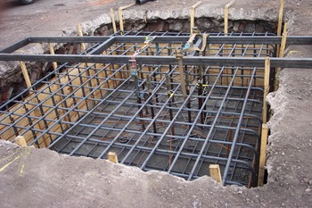
(5) Improper location of reinforcing steel: This section refers to reinforcing steel that is improperly located or is not adequately secured in the proper location.
Either of these faults may lead to two general types of problems. First, the steel may not function structurally as intended, resulting in structural cracking or failure. A particularly prevalent example is the placement of welded wire mesh in floor slabs. In many cases, the mesh ends up on the bottom of the slab which will subsequently crack because the steel is not in the proper location. The second type of problem stemming from improperly located or tied reinforcing steel is one of durability. The tendency seems to be for the steel to end up near the surface of the concrete. As the concrete cover over the steel is reduced, it is much easier for corrosion to begin.
(6) Movement of formwork: Movement of formwork during the period while the concrete is going from a fluid to a rigid material may induce cracking and separation within the concrete. A crack open to the surface will allow access of water to the interior of the concrete. An internal void may give rise to freezing or corrosion problems if the void becomes saturated.
(7) Premature removal of shores or reshores: If shores or reshores are removed too soon, the concrete affected may become overstressed and cracked. In extreme cases there may be major failures.
(8) Settling of the concrete: During the period between placing and initial setting of the concrete, the heavier components of the concrete will settle under the influence of gravity. This situation may be aggravated by the use of highly fluid concretes. If any restraint tends to prevent this settling, cracking or separations may result. These cracks or separations may also develop problems of corrosion or freezing if saturated.
(9) Settling of the subgrade: If there is any settling of the subgrade during the period after the concrete begins to become rigid but before it gains enough strength to support its own weight, cracking may also occur.
(10) Vibration of freshly placed concrete: Most construction sites are subjected to vibration from various sources, such as blasting, pile driving, and from the operation of construction equipment. Freshly placed concrete is vulnerable to weakening of its properties if subjected to forces which disrupt the concrete matrix during setting.
(11) Improper finishing of flat concrete surface: The most common improper finishing procedures which are detrimental to the durability of flat concrete surface are discussed below:
  • Adding water to the surface: Evidence that water is being added to the surface is the presence of a large paint brush, along with other finishing tools. The brush is dipped in water and water is “slung” onto the surface being finished.
  • Timing of finishing: Final finishing operations must be done after the concrete has taken its initial set and bleeding has stopped. The waiting period depends on the amounts of water, cement, and admixtures in the mixture but primarily on the temperature of the concrete surface. On a partially shaded slab, the part in the sun will usually be ready to finish before the part in the shade.
  • Adding cement to the surface: This practice is often done to dry up bleed water to allow finishing to proceed and will result in a thin cement-rich coating which will craze or flake off easily.
  • Use of tamper: A tamper or “jitterbug” is unnecessarily used on many jobs. This tool forces the coarse aggregate away from the surface and can make finishing easier. This practice, however, creates a cement-rich mortar surface layer which can scale or craze. A jitterbug should not be allowed with a well designed mixture. If a harsh mixture must be finished, the judicious use of a jitterbug could be useful.
  • Jointing: The most frequent cause of cracking in flatwork is the incorrect spacing and location of joints.

QUANTITY & RATE ANALYSIS FOR REINFORCED CONCRETE


Today we will see how to prepare rate analysis for Reinforced Concrete (RCC) work. First step to rate analysis is the estimation of labour, materials, equipments and miscellaneous items for particular quantity of reinforced concrete.
The second step is to determine the component of structure for which the RCC rate analysis is required, as the quantity of reinforcement steel varies with slabs, beams, columns, foundation, RCC Roads etc., though the quantity of other materials like sand, coarse aggregate and cement remain the same with the same mix design (mix proportion) of concrete. Labour rates for reinforcement work changes with type of structural component as the quantity of reinforcement steel changes. The Quantity of materials like sand, cement and coarse aggregates vary with mix design such as M15 (1:2:4), M20 (1:1.5:3), M25, M30 etc..
reinforced-concrete
Here we will see the rate analysis for 1m3 of reinforced concrete.

Data required for RCC Rate Analysis:

1. Estimation of materials:
Material estimation include sand, cement, coarse aggregate and steel for a particular mix design. Let us consider a mix design of 1:1.5:3 for our estimation practice. The dry volume of total materials required is considered as 1.54 times the wet volume of concrete, due to voids present in sand and aggregates in dry stage. Therefore, for our calculation, we will consider the total volume of materials required as 1.54 m3 for 1 m3 of wet concrete.
a) Bags of cement required:
Volume of cement required for 1m3 of Concrete =
=0.28 m3
Then number of bags of cement (volume of one bag of cement = 0.0347 m3)
== 8.07 bags of cement.
b) Volume of Sand required:
Volume of sand required =  = 0.42 m3 of sand.
c) Volume of Coarse Aggregate Required
Volume of Coarse Aggregate == 0.84 m3 of coarse aggregates.
d) Estimation of Reinforced Steel:
Quantity of steel required depends on components of structure, i.e. slabs, beams, columns, foundations, roads etc. To estimate the steel required, there are two methods.
First method is, when we have the drawing available, we can calculate the total weight of steel required divided by total volume of concrete for different components. This will give us the weight of reinforcement steel per cubic meter of concrete.
Second method is assuming the percentage of reinforcement for different components. Following are the percentage of reinforcement steel generally required per different components. Its values can vary from structure to structure, and can be assumed from past experiences of similar structure.
  • For slabs = 1.0 % of concrete volume.
  • For Beam = 2 % concrete volume.
  • For column = 2.5 % of concrete volume.
  • For RCC Roads, 0.6% concrete volume.
Lets take example of RCC Column, where reinforcement required is 2.5% of concrete volume, weight of steel required will be:
=196.25 kg.
2. Labour Requirement for 1m3 of RCC:
Labours required are presented in terms of days required by particular labour to complete its work for the given quantity of concrete. Following are the various labours required:
a) Mason: As per Standard Schedule of Rates and Analysis of Rates, One mason is required for 0.37 days.
b) Labours: One Unskilled labours required for 3.5 days.
c) Water carrier: One water carrier required for 1.39 days.
d) Bar Bender: Bar bender requirement depends on weight of reinforcement. Lets consider one bar bender required for 100 kg of steel as for 1 day.
e) Mixer Operator: One mixer operator required for 0.0714 days.
f) Vibrator Operator: One vibrator operator required for 0.0714 days.
3. Equipments and sundries:
Equipment and other charges, such as water charges, miscellaneous items, tools and tackles etc can be assumed as some percentage of total cost of materials and labours. Lets say it as 7.5%.
4. Contractor’s Profit:
Contractor’s profit depends on place to place, organization to organization and work to work. It varies from 10 – 20%. For our case lets assume it as 15% of total cost of materials, labours and equipments.
We have calculated the quantity of every item in above 1 – 3 steps. For rate analysis of RCC, we need to multiply each quantity with their rates to get the amount for every item of work. Rates vary from place to place and time to time. It is advisable to assume local rates or standard rates of the place.
The sum total of all the four items above will give the rate or cost for 1m3 of concrete.

Disqus Shortname

Comments system